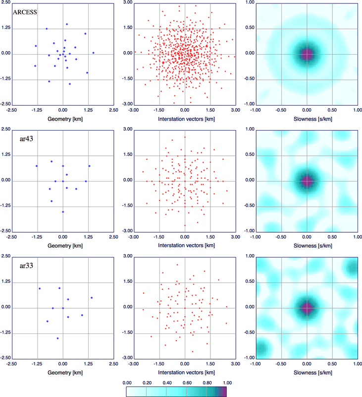
We illustrate the relation between the spiral-arm array design and more conventional multi-ring circular arrays by comparing the geometry and response of the ARCESS array in northern Norway with three-arm array configurations with many fewer stations. In Figure S1, we display the geometry, interstation vectors, and array response function for the ARCESS array with 25 stations and for two spiral-arm configurations with 13 and 10 stations that achieve comparable slowness resolution in the neighborhood of the target. The array response function scales inversely with the radius of the array, so the size of the central peak is about five times larger than in the examples shown in Figure 4 of the main paper.
The ARCESS array was designed to achieve a very uniform azimuth response (e.g., Schweitzer et al., 2009) and does indeed produce a very symmetrical peak. The main-ring side lobe with amplitude about 0.1 is displaced to 0.6 s/km from the target slowness so will rarely impede the analysis of regional arrivals. The outer side lobes (around 2.0 s/km) reach an amplitude of 0.2 at most.
We compare this well-established and effective array design with two spiral-arm array concepts using fewer stations, which can be regarded as thinned versions of the circular array. The first version, ar43, has four rings as in ARCESS, but they are evenly spaced along the three arms for a total of 13 stations. The ar43 response out to the 0.6 s/km side-lobe ring is nearly as good as for the denser ARCESS array, and indeed the threshold is a little lower (amplitude 0.06). The central lobe has a very similar configuration to ARCESS. The symmetry of the spiral-arm pattern is reflected, as expected, in the outer pattern of array response side lobes, which reach amplitude 0.15, at most, out to slowness separations of 1.0 s/km. The reduced number of sensors means that the sampling in interstation space drops significantly, but a good distribution of interstation vectors is still achieved.
For very large slowness offsets from the target (outside the domain illustrated), the side lobes for ARCESS remain low; however, for the thinned array ar43, they increase to reach almost 0.5 in amplitude in some azimuths at slowness shifts greater than 2.0 s/km (compare with Figure 4 in the main paper). These large distant side lobes will not cause any problem with analysis unless there is interference from exceptionally slow arrivals.
It is even possible to drop the number of stations a little further by employing only three rings for a total of 10 stations. The second version, ar33, still has a well-defined target peak, but now it is not quite as uniform with azimuth. More prominent side lobes now appear, with amplitude 0.17 at a separation of around 0.9 s/km from the target, which are unlikely to cause significant problems in analysis. However, by 1.2 s/km from the target, strong side lobes already reach a maximum amplitude of 0.4.
Although the spiral-arm arrays are insensitive to minor changes in sensor position, and even loss of sensors, we have found the 13-station configuration represents a good compromise between number of sensors and good array response. This design has therefore been used in multiple deployments of small arrays for surface characterization studies on scales comparable to those displayed in Figure S1.
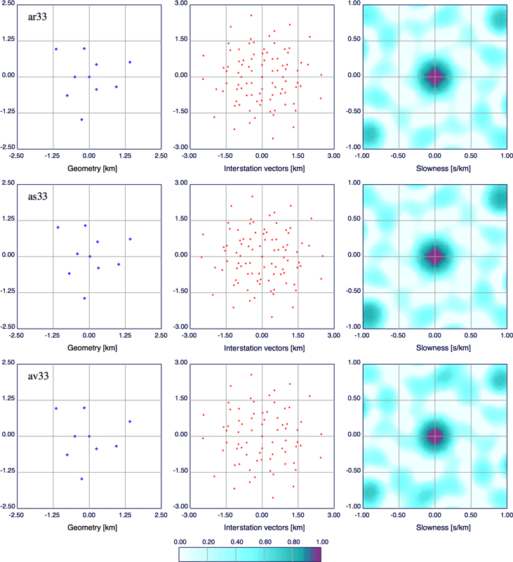
A good feature of the spiral-arm design is that the array response function is not very sensitive to the precise placing of the sensors. We illustrate this aspect in Figure S2, where we show the 10-station array ar33 in the upper panel followed by two variants: as33 with shifted stations and av33 with a missing station.
In practical deployments, it is rare that logistical considerations allow sensors to be placed exactly at the design points. For the array as33 (middle panel of Figure S2), we introduced random perturbations of up to 50 m in each horizontal coordinate (i.e., up to 2% of the array aperture); these shifts are enough to be seen in the array configuration. The effect on both the array response and the pattern of interstation vectors is small. The outer side lobes are a little enhanced, but no discrimination capability is lost in the zone out to 0.5 s/km in slowness from the target. Beyond a slowness separation from the target of 1.1 s/km, the first sideband ring reaches an amplitude of 0.5, but those farther out are very similar to that for ar33.
If we drop a station, as in array av33 in the bottom panel in Figure S2, the effect is more significant. Yet we have not lost much, because the side lobes in the response in the slowness zone out to 0.5 s/km from the target remain quite small (amplitude less than 0.25), and are comparable to ar33 for large slowness separations. The distribution of interstation vectors is not as good as in the regular design for ar33, and there are fewer pairs but still enough to be useful.
As noted above, we favor the use of 13 (or more stations) in temporary deployments of such arrays, because this gives additional resilience to the experimental design as implemented.
Figure S1. Comparison of the performance of array designs of equivalent aperture, showing the array geometry, the interstation vectors, and the array energy response. The same linear scale for the array response is used as for Figures 1–4 in the main paper. (top) The ARCESS regional array in northern Norway, with four concentric rings and a total of 25 sensors, achieves a well-defined central peak and a very low and uniform background in the array response function. (middle) A three-arm spiral design with four rings and a total of 13 stations is shown, for which the main lobe is comparable to ARCESS, though not quite as uniform in azimuthal response. (bottom) A configuration with just 10 stations achieves a very low level of side lobes in the array response function out to 0.5 s/km from the target.
Figure S2. Influence of changes in array configuration for a simple three-arm spiral array design for (a) ar33, the 10-station configuration illustrated in Figure S1; (b) as33, an array with random perturbations of up to 50 m in the horizontal offset; and (c) av33, an array with a missing station. The array response function stays stable under the influence of minor changes, but side-lobe energy rises a little when a station is lost.
Schweitzer, J., J. Fyen, S. Mykkeltveit, and T. Kvaerna (2009). Seismic arrays, Chapter 9, in New Manual of Seismological Observatory Practice, International Association of Seismology and Physics of the Earth’s Interior (IASPEI), available from http://nmsop.gfz-potsdam.de (last accessed November 2014).
[ Back ]