| Publications: SRL: Electronic Seismologist |
November/December 2005
Automated Receiver Function Processing
H. Philip Crotwell and Thomas J. Owens
Department of Geological Sciences
University of South Carolina
Columbia, SC 29208
Phone: +1-803-777-4530
Fax: +1-803-777-0906
E-mail: crotwell@seis.sc.edu, owens@sc.edu
Introduction
The aim of this is article is twofold: first to introduce an automated processing system based on SOD (Standing Order for Data, http://www.seis.sc.edu/SOD/) (Owens et al., 2004), and second to give some initial results and pitfalls from our experience with using this system for automated receiver function calculations. EARS, the EarthScope Automated Receiver Survey, aims to calculate bulk crustal properties for all stations within the continental United States that are available from the IRIS DMC using receiver functions and to distribute these results to interested research and education communities as a “product” of the USArray component of EarthScope. Because of the high level of automation that this requires, a natural extension of this effort is to calculate similar results for all stations in the IRIS DMC. To do this we have employed SOD, a FISSURES/DHI-based software package (Ahern, 2001a, b) that we have developed to do automated data retrieval and processing.
We introduce EARS as an example of what we term “receiver reference models.” They are standard analysis techniques applied to stations. These are analogous to the Harvard Centroid Moment Tensor solutions (which could be termed source reference models). An RRM need not be a definitive result but rather provides a standard, well known, globally consistent reference. This may be sufficient for many users, just as CMT’s are sufficient for many, but may also be a starting point for more in-depth, focused studies. The key features of an RRM are that it be generated from a well known and widely accepted technique, produce results for most or all stations, and provide updated results as new sources of data become available. In addition, it must produce results that are of interest in a form usable by the community.
Because automated processing proceeds, by definition, without a large amount of human input and guidance, there are differences between it and traditional seismic processing. An automated system must rely on quantitative measures of quality as opposed to the seismologist’s insight into what constitutes a “good” or “bad” earthquake or seismogram. The advantage of non-human-driven processing is that the volume of data to be used can be substantially larger. Use of these larger data volumes can have quality implications as well, making use of stacking techniques and statistics instead of intuition and detailed analysis by a seismologist. If a seismic technique can be structured so that it can be driven by SOD, then there is really no reason not to apply it to as large a volume of data as possible. Hence, we envision the RRM as just the first of many automated products, created by us and by others.
EARS is a work-in-progress. In this article, we emphasize the methods used and the pitfalls encountered in our initial processing of all magnitude 5.5 or above earthquakes for all stations in the IRIS POND. We have not yet begun to interpret the results in terms of their implications for Earth structure. Most of our effort to date has been in developing the system. We still have considerable work to do to improve our ability to differentiate reliable results from stations where the automated system produces values of dubious quality. All data and results for EARS are available at http://www.seis.sc.edu/ears/.
Automated Processing with SOD
SOD, the Standing Order for Data, is a freely available Java-based software package for automated retrieval and processing of seismic data. It is built on top of DHI, the data-handling infrastructure, which is a CORBA-based system to access network/channel information, event data, and seismograms. To use SOD, the user sets up an XML configuration file, a “recipe” in SOD parlance, which specifies the types of earthquakes, channels, and seismograms that she is interested in. The level of specification is fine-grained and flexible, allowing a high degree of customization. In addition to data selection and rejection, SOD can also apply processing to the data as they are retrieved, saving much time and effort. SOD is designed to be a long-running background application and can either mine historical data or wait for earthquakes and process them as they occur. Two Web-based examples of SOD that may be of interest are REV, the Rapid Earthquake Viewer, http://rev.seis.sc.edu/, and USArrayMonitor, http://usarray.seis.sc.edu/. REV is a Web-based, quick seismic data viewer aimed at the E&O community, while USArrayMonitor is an outreach tool that allows landowners and others easy access to the data recorded by their local USArray stations. Downloading instructions and more information about SOD can be found at http://www.seis.sc.edu/SOD/.
Overview of SOD
In order for SOD to retrieve and process seismograms, it needs two basic pieces of information, a channel and a time window. The time window in SOD is based on an earthquake, or event, and so this naturally leads to a separation of the configuration into three sections, or arms: one for channels, one for events, and a third for the combination of events and channels resulting in seismograms.
The first is the network arm, which controls which networks, stations, and channels are acceptable. There is considerable flexibility in deciding which are acceptable, based on attributes such as network, station and channel code, location, active time, and distance from a fixed location. Each of these can be combined within logical ands, ors, and nots, allowing the creation of very complex criteria built up from simple pieces. In addition, there are channel processors that can do such tasks as save the instrument response as a resp or sac polezero file and plot the station on a map.
The event arm selects earthquakes of interest, first based on a coarse selection of location, magnitude, depth, catalog, and time. Finer-grained selection is then possible using each of these as well as distance, azimuth, and back-azimuth from a point and linear distance, with magnitude from a point. As with the network arm, logical combinations of all the above are possible.
The waveform arm combines the results of the two previous arms, creating event-channel pairs that are used to retrieve and process seismograms. These event-channel pairs can also be selected based on properties such as distance, azimuth, back-azimuth, existence of phases, and locations of midpoints. The time window is determined based on phases and the event and channel, with further selection based on the actual seismic data.
Once SOD has retrieved seismograms, it can apply a suite of processing steps, including built-in processors such as filtering, mean removal, instrument correction, cutting, and signal to noise. In addition, SOD is extensible via externally written processors. This is what we have done with EARS, using the built-in SOD functionality to preprocess the seismograms and then using an external custom processor to create the receiver functions.
EARS
Method
The receiver functions and crustal estimates within the EARS system are calculated in a completely automatic fashion using the iterative deconvolution technique of Ligorria and Ammon (1999) and the H-K stacking technique of Zhu and Kanamori (2000). The stacking is done with the phase-weighted stacking technique of Schimmel and Paulssen (1997). SOD is used for the data retrieval, preprocessing, and receiver function calculation. The receiver functions are then stored in a database and the stacks are created by a separate process.
The iterative deconvolution technique of Ligorria and Ammon (1999) is well suited to automated processing because of its stability. The calculation of receiver functions by frequency-domain deconvolution involves stabilization techniques such as water-level deconvolution (e.g., Owens et al., 1984) that are not easily automated because of parameters that often must be tuned to each seismogram. The iterative method, by contrast, is easy to automate, as it does not need to be tuned to individual seismograms.
The H-K stacking technique of Zhu and Kanamori (2000) is also very compatible with automation. It considers a grid of crustal thickness, H, and Vp / Vs values, K. Each (H, K) pair, along with an assumed Vp, corresponds to a crustal model for which predicted times can be calculated for each of the three main reverberations, Ps, PpPs, and PsPs/PpSs, on each receiver function. The amplitudes for each time are extracted from the receiver function and the sum taken over all receiver functions at that station, noting that the polarity of PsPs/PpSs is reversed. The global maximum over this grid is taken to be the best crustal model.
Data Selection
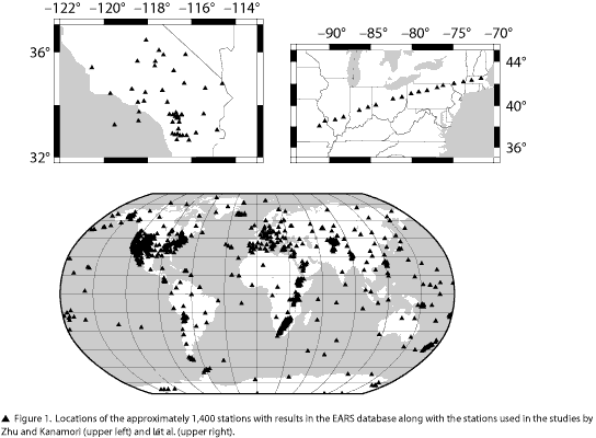
We have processed all broadband channels for all stations available from the POND at the IRIS DMC, including both temporary and permanent stations. This has given us at the present time about 1,400 stations (Figure 1). All events above magnitude 5.5 in the WHDF catalog from the NEIC are processed. For each of these events, the seismograms are retrieved and preprocessed for all stations with broadband data between 30 and 100 degrees for which the P phase exists in the PREM model. If the seismograms meet the quality constraints, such as no gaps and a signal to noise ratio of at least 2, then receiver functions are calculated and stored in a database. Only events-station pairs for which the iterative deconvolution has a greater than 80% match are used in the resulting stacks.
Processing
A standard set of processing steps is taken for all event-station pairs. First, a window from 120 seconds before the P wave to 180 seconds after the P wave is requested from the IRIS DMC. Any seismograms containing gaps, or for which there are not three components, are rejected. We then calculate a simple signal to noise comparing the variance of a long time window, from 105 to 5 seconds before the predicted P-wave arrival, with the variance of a short time window, from 1 second before to 5 seconds after the predicted P arrival. This is not the same as traditional short- to long-term signal to noise ratios, but provides a similar measure of the usefulness of the P-wave arrival. Earthquakes for which the maximum signal to noise is less than 2 for all components are rejected.
A cut operation is then performed to window the data from 30 seconds before the predicted P-wave arrival time to 120 seconds after this time in preparation for the deconvolution. Predicted P-wave times are calculated using that TauP package (Crotwell et al., 1999) using the PREM model (Dziewonski and Anderson, 1981). The mean and trend are removed, a taper is applied, and the overall gain from each channel’s response is applied. We do not apply a full instrument deconvolution, instead assuming that the response is relatively flat in the passband of interest. The data are then filtered with a Butterworth bandpass filter from 50 seconds to 5Hz.
All of the processing steps to date are done using SOD’s built-in processors before the data ever land on a hard disk at our institution.
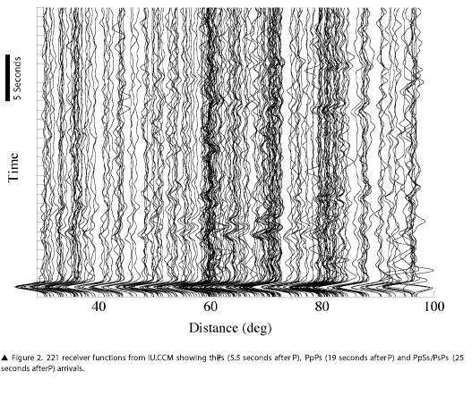
The iterative deconvolution is then applied to the data via an external processor launched by SOD. This deconvolution uses a Gaussian width of 2.5. The iteration is limited to 400 steps or a percentage match of 99.99, which effectively means that all 400 steps are almost always applied. Both radial and transverse receiver functions are calculated and are then stored in the database, along with the original seismograms, regardless of the percentage match that they achieve. At this point, SOD’s job is done. The populated database is then accessed by a separate program that performs the stacking and bootstrap tasks. Separating this from SOD allows us to schedule these tasks at regular intervals, rather than restacking every station each time a new event is added by SOD. Figure 2 shows example receiver functions from station IU.CCM, which has visible converted phases at about 5.5 seconds for Ps, 19 seconds for PpPs, and 25 seconds for PpSs/PsPs.
Stacking
Because low percentage match receiver functions are often contaminated with noise or lack signal, we do not stack receiver functions for which the percentage match is below 80. For some stations, especially within short-lived temporary deployments, this severely limits the number of receiver functions with the stacks; however, for an automated system this seems a reasonable threshold. The stacking technique of Zhu and Kanamori (2000) is based on the transformation of the amplitudes of the receiver function from the time-domain into a system based on crustal thickness (H) and Vp/Vs ratio, (K) by using the predicted times of the 3 principal crustal reverberations, Ps, PpPs and PsPs/PpSs. These predicted times also depend on an assumed Vp, although the results are relatively insensitive to it. We have chosen to use the Vp from the Crust2.0 model (Bassin, 2000) in order to have a reasonable value that still varies across the globe. We feel this is more appropriate than a simple constant Vp as it takes into account large scale regional variations in Vp. Once this transformation to the H-K system has been done, the amplitudes no longer have a time dependency, which eliminates the ray parameter as a variable. Thus, earthquakes at different distances, with correspondingly different ray parameters can be stacked. Once the stacks are calculated, the thickness and Vp/Vs corresponding to the maximum value of the stack are taken to be the estimate of the bulk crustal properties.
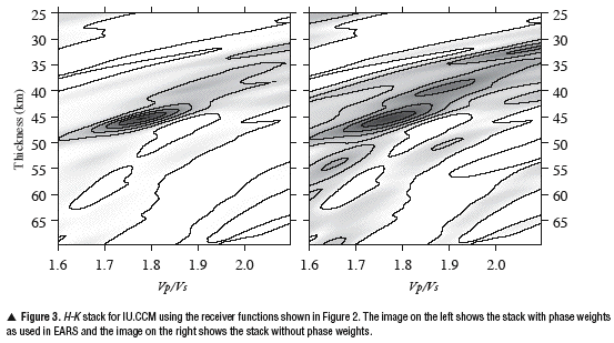
In addition to this stacking idea based on predicted arrival times, we also make use of phase weights for the stacks (Schimmel and Paulssen, 1997). This is a nonlinear stacking technique that weights the straight amplitude stack by the square of a sum of unit magnitude complex values constructed from the instantaneous phase of the receiver function. In areas where the receiver functions have similar phases, these complex values will sum constructively, yielding a multiplication factor close to unity. In areas where the phase varies greatly across the receiver functions, they will sum destructively, yielding a multiplication factor near zero. Thus, this technique greatly sharpens the stacks for coherent signals and dampens incoherent signals at the little expense of calculating the Hilbert transform of the receiver functions. Figure 3 shows a stack for IU.CCM both with and without the phase weighting. The phase-weighted stack does not have local maxima of similar amplitude as the maximum and the global maximum is sharper.
Error Estimation
Error estimation, both to define the true error as well as to separate valid results from unusable results, is especially important in an automated system. We have made use of a bootstrap technique (Efron and Tibshirani, 1991) to provide meaningful representations of the error. This involves the creation of a new set of receiver functions at each station by randomly sampling with replacement from the original set. The sampled set has the same size as the original but may contain duplicates of some receiver functions. A stack is calculated from this new set and the global maximum is noted. The resampling procedure is repeated for some number of tries, 100 in our case, to produce a set of thickness and Vp/Vs values on which a standard deviation can be calculated. It is important to note that this standard deviation has a different meaning in the case of a single well defined global maximum as opposed to many local maxima, none of which is significantly different from the others. In the first case, the error estimate reflects the broadness of the peak and indicates a true uncertainty in the values. In the second case, the global maxima of each individual bootstrap may correspond to a different local maximum from the original stack. Thus, the error in this case is more of an indication that there are several possible interpretations and the system is not able to differentiate between them. Generally, small standard deviations indicate a single maximum, and larger values indicate multiple similar local maxima. Thus, stations with large standard deviations should be reviewed by an analyst before there can be any confidence in the result.
We also tried an error estimate based on the curvature of the maximum (Zhu and Kanamori, 2000) but found that this estimate often produced errors that are too small to be realistic. The curvature estimate is also unaffected by the presence of local maxima and is hence less useful for separating good results from those requiring additional analysis.
Comparison with Prior Results
Because of the automated nature of this study, a comparison with prior results is of great interest. We make comparisons with two studies to understand how well the automated system can do without resorting to a seismologist’s intuition for reasonable and unreasonable results.
Zhu and Kanamori
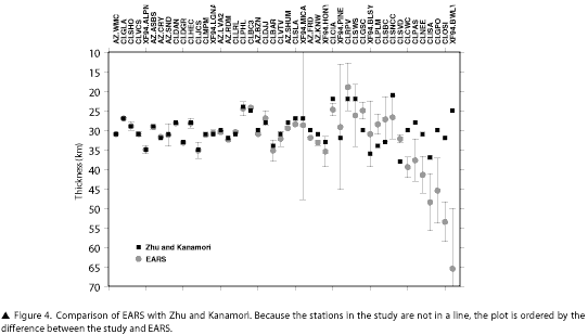
Zhu and Kanamori (2000) introduced the H-K stacking method most similar to what we use in EARS. They analyzed stations in Southern California from the AZ, CI, and XF94 networks. The agreement of their results and the preliminary results of EARS is overall very good (Figure 4), with 32 of the 46 stations having differences of less than 3km and 39 of 46 differing by less than 6km. The remaining seven stations have much larger standard deviations, but each has a local maximum that matches well, indicating that improved processing algorithms and/or human input could resolve these differences. It is worth noting that the four largest error estimates are from the temporary XF94 network, likely due to the short duration of this deployment relative to permanent stations.
MOMA
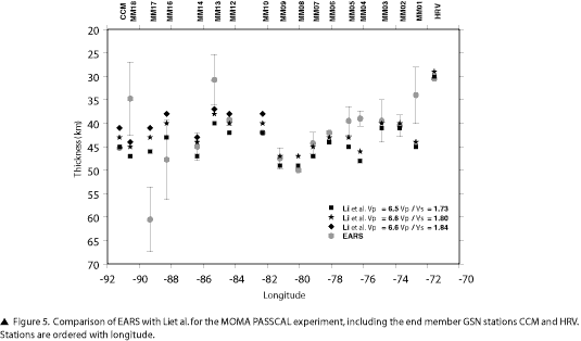
The Missouri to Massachusetts Transect PASSCAL experiment provides a good opportunity for comparison with EARS because the duration of the deployment is similar to the planned USArray Transportable Array stations. The MOMA experiment deployed 18 stations forming a line between IU.CCM, Cathedral Cave, Missouri, and IU.HRV, Harvard, Massachusetts. Li et al. (2002) estimated crust and upper-mantle structure using receiver functions. They used a suite of three assumed crustal P velocities and Vp/Vs ratios: 6.6km/s with 1.84, 6.6km/s with 1.80, and 6.5km/s with 1.73, generating up to three crustal thickness estimates for each station. They did not generate crustal thickness estimates for two stations, MM11 and MM15. Figure 5 shows a comparison of the results of their receiver function analysis with those of EARS for crustal thickness versus longitude. Overall there is good agreement, with stations in the western end showing the largest differences.
The eastern stations, with the exception of MM01, generally fall within or near the estimates of Li et al. (2002). MM04 through MM07 are in a region that has a significantly different Vp in the Crust2.0 model from those used in the MOMA study, almost .5km/s slower. Because the crustal thickness varies close to linearly with Vp, with a .1km/s increase in Vp causing almost a .5km increase in crustal thickness, it is easy to attribute up to 2.5km of the difference for these stations just to the assumed Vp. EARS shows MM01 with a crust 10km thinner than the closest estimate and with relatively large standard deviation. There is a single global maxima at 34km and no local maxima that might correspond to a 45-km crust, leaving little explanation for the difference. The EARS value of 34 is midway between the two adjoining stations of IU.HRV and MM02, which agree well in both studies.
The western stations are more of a problem, with MM13, MM16, MM17, and MM18 showing large standard deviations in EARS and significant differences with Li et al. (2002). Of these, MM16 has the smallest difference, 5km deeper, and has the most compelling thickness versus Vp/Vs maxima. While the error bars are large at this station, due to local maxima influencing the bootstrap, it is consistent with neighboring stations MM14 and MM17 in Li et al. (2002). MM13 and MM18 are more of a problem, as both are shallower in EARS, 6km and 9km respectively, and significantly different from neighboring stations. MM13 has a local maxima at 43km that would be more consistent with both Li et al. (2002) as well as a more reasonable Vp/Vs ratio, and is hence likely a case of the correct maxima not being the global maxima in the stack. MM18 is more variable but does not have any maxima that might correspond to a 44–47-km crust. Due to the large standard deviations at these four stations, along with MM01, they are probably indicators of problems in the automated system and may require an analyst to make a quality judgment. As with all temporary seismic networks, the number of earthquakes is small relative to permanent stations. This may explain why the two permanent stations at the ends of the array have very good agreement in both studies, as well as very small standard deviations in EARS.
Problems and Pitfalls
The most obvious problem to encounter while dealing with results of an automated system unleashed on the entire IRIS data archive is the sheer volume of data, along with the computer time to process it. In the EARS case, we have found that storage is not as difficult of a problem as computation time. Disk space is plentiful, cheap, and easy to add. Computational ability is more expensive to add, and the needed parallelizations can be more complex to deal with. For EARS, the most costly step in terms of CPU time is the calculation of the receiver functions. In order to insulate ourselves from having to repeat this, we store the calculated receiver functions in a database and then perform the stacking and analysis separately. This also has the advantage of allowing the use of multiple machines to parallelize the computations. We make use of a central PostgreSQL database with separate instances of SOD running on four to six Macintosh computers. Each separate run of SOD works on either a different time interval or a different network, allowing a simple, yet effective, sharing of the workload. An advantage of SOD is that it is written in Java and so is platform-independent, and so we could use a mixed network if it were available.
Not as costly as the receiver function calculation, but still nontrivial, is the bootstrap error estimation. We have addressed this in a similar way, by spreading the resampling across multiple computers on our network. One further problem, due to the fact that we want to process new earthquakes and stations as they become available and that the bootstrap is time-consuming, is that each time an earthquake occurs, the bootstrap for many stations will need to be redone. We do not have an ideal solution to this problem but will likely redo the bootstrapping on only a periodic basis. Because up-to-the-minute results are not as important with a study such as EARS, this should not be a problem.
One difficulty with the H-K technique of Zhu and Kanamori (2000) is the nonuniqueness of the maxima. Although one would like the global maximum always to correspond to the true bulk crustal properties, the presence of noise and complex structure, as well as stations with small amounts of data, often results in multiple local maxima, and choosing among them simply based on amplitude may not be wise. Implicit in the technique is the choice of valid ranges for crustal thickness and Vp/Vs. The choice of ranges influences the resulting global maximum, as a maximum outside of an overly restrictive grid is excluded while an overly liberal grid includes nonphysical maxima. We have chosen to make our grid liberal and inclusive to begin with to cover the wide range of global crustal properties. Crustal thickness varies from 10km to 70km and Vp/Vs from 1.6 to 2.1. While all nonoceanic crust is likely to fall within this range, it is also likely to include maxima that are highly improbable in large parts of the world. The challenge is then to restrict this grid further using a priori knowledge for the region around each station. As a first step in this direction, we limit the minimum crustal thickness to 25km as long as the crustal thickness in the Crust2.0 model (Bassin, 2000, http://mahi.ucsd.edu/Gabi/rem.html) is greater than 30km, otherwise limiting the minimum to 5km less than the Crust2.0 value. This helps exclude reverberations from shallow basins that often produce local maxima that can confuse the system. A limit on the maximum depth is also likely needed, although we have not experimented with one yet. A limit on the Vp/Vs would also be useful, but Crust2.0 is nearly constant with respect to Vp/Vs and so another source would need to be found. We are being cautious in implementing too many “a priori” constraints, as there is also the danger of overconstraining the system so that it can reproduce only the “a priori” result rather than reveal new information on bulk properties.
Another issue not often considered is what to do with the results. A traditional seismic analysis might present the results of a few dozen stations, and the results and interpretation can easily fit into a journal article. With a project such as EARS, we have results from on the order of a thousand stations across the entire globe. Another complication is that we intend for EARS to continue processing future earthquakes and stations that do not exist yet; the arrival of a new station within USArray every day or two dramatically illustrates this point. We have chosen to make the results of EARS available by creating a Web-based interface to the same database that we used in the processing stage. This is a double-edged sword, giving the greater community access to the latest results, but also not protecting them from the inevitable influence of bad data or Earth structure too complicated for the automated system. “Buyer beware” might be the best that can be done for the research community. For the education community, we need to consider ways to insulate users better from spurious, and potentially confusing, results.
Of course putting results “on the Web” is much easier said than done. The scientific calculations are certainly the bulk of the work, but designing a pleasing, useful, and efficient interface into a database such as EARS has is definitely nontrivial. We are continuing to refine and extend the Web front end for the EARS project. It currently allows access to individual stations via their networks as well as via summaries of comparisons with several previous studies. Each station page includes information about the station, a summary of the EARS result, a plot of the H-K stack, and a listing of all the earthquakes processed for that station. In addition, the stack can be downloaded as an ASCII xyz file, and the receiver functions used in the stack can be downloaded as a Zip file of SAC-formatted seismograms. Each earthquake for the station has a subpage with information about the event, the H-K plot for that earthquake only, and images of the original seismograms and the receiver functions. We will extend the capabilities of these pages over time to allow more sophisticated browsing and searching as well as downloading of original data and results.
Acknowledgements
EARS is supported by the EarthScope Program, NSF grant #EAR0346113.
References
- Ahern, T. (2001a). Data handling infrastructure at the IRIS DMC, IRIS DMC Newsletter 3(1), 3 (http://www.iris.edu/news/newsletter/vol3/no1/page3.htm).
- Ahern, T. (2001b). What happened to FISSURES?—or—Exactly what is the data handling interface?, IRIS DMC Newsletter 3(3), 3 (http://www.iris.edu/news/newsletter/vol3/no3/page3.htm).
- Bassin, C., G. Laske, and G. Masters (2000). The current limits of resolution for surface wave tomography in North America (abstract), Eos, Transactions of the American Geophysical Union 81, F897 (http://mahi.ucsd.edu/Gabi/rem.html).
- Crotwell, H. P., T. J. Owens, and J. Ritsema (1999). The TauP Toolkit: Flexible seismic travel-time and ray-path utilities, Seismological Research Letters 70, 154–160.
- Dziewonski, A. M. and D. L. Anderson (1981). Preliminary reference Earth model, Physics of the Earth and Planetary Interiors 25, 297–356.
- Efron, B. and R. Tibshirani (1991). Statistical data analysis in the computer age, Science 253, 390–395.
- Li, A., K. M. Fischer, S. van der Lee, and M. E. Wysession (2002). Crust and upper mantle discontinuity structure beneath eastern North America, Journal of Geophysical Research 107, B5, 2100, doi:10.1029/2001JB000190.
- Mooney, W. D., G. Laske, and T. G. Masters (1998). CRUST5.1: A global crustal model at 5° × 5°, Journal of Geophysical Research 103, 727–747.
- Owens, T. J., H. P. Crotwell, C. Groves, and P. Oliver-Paul (2004). SOD: Standing Order for Data, Seismological Research Letters 75, 515–520.
- Owens, T. J., G. Zandt, and S. R. Taylor (1984). Seismic evidence for an ancient rift beneath the Cumberland Plateau, Tennessee: A detailed analysis of broadband teleseismic P-waveforms, Journal of Geophysical Research 89, 7,783–7,795.
- Schimmel, M. and H. Paulssen (1997). Noise reduction and detection of weak, coherent signals through phase-weighted stacks, Geophysical Journal International 130, 497–505.
- Zhu, L. and H. Kanamori (2000). Moho depth variation in Southern California from teleseismic receiver functions, Journal of Geophysical Research 105, 2,969–2,980.
SRL encourages guest columnists to contribute to the "Electronic Seismologist." Please contact Tom Owens with your ideas. His e-mail address is owens@sc.edu.
Posted: 15 December 2005

